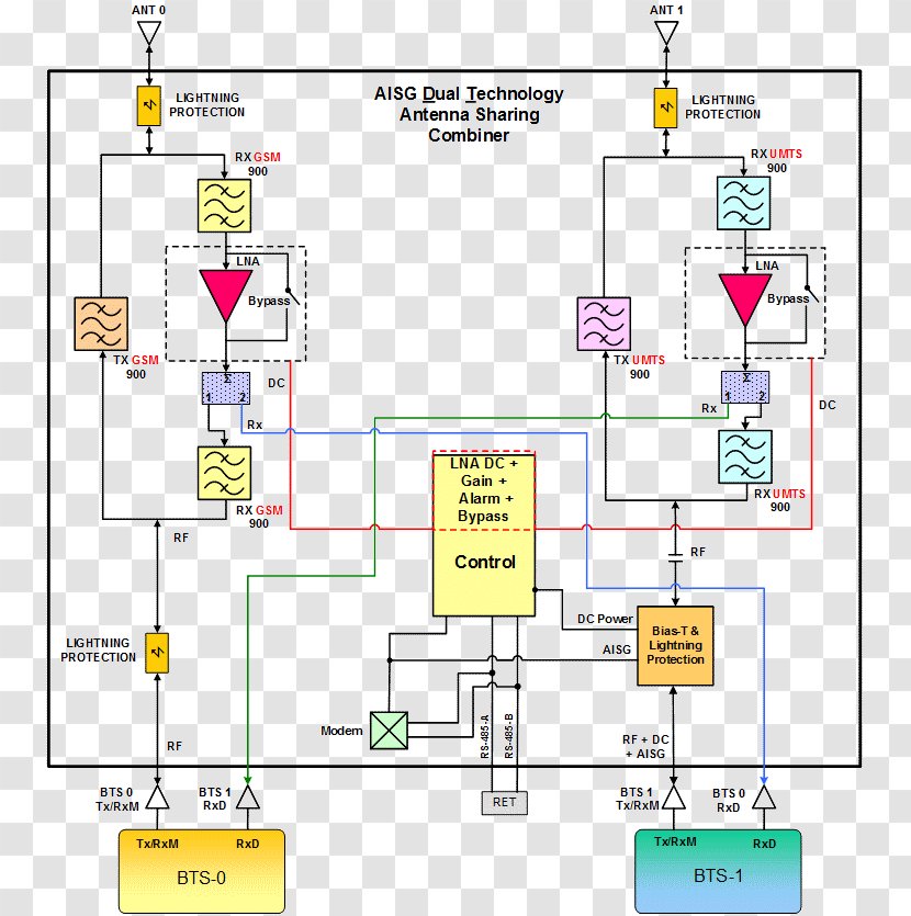
A block diagram of a control system. It consists of various components such as resistors, capacitors, transistors, and diodes. The main component of the system is the control panel, which is located in the center of the block. The control panel is used to control the flow of electricity and other electrical components. There are several components in the system, including the resistors and capacitors. The resistors are connected to the capacitors and transistors. The capacitors are used to regulate the voltage and current in the circuit, while the transistors are used for controlling the current and voltage levels. The diode is used as a voltage regulator, which helps to regulate voltage levels in the electrical system. The circuit also has a control switch, which allows the user to switch between the two components to control their current and current levels. - The control switch is connected to a power supply, which can be used to power the system from a distance. The power supply is then used to supply the current to the voltage regulator. The voltage regulator can also be used as an indicator to monitor the current flow and prevent the current from entering the system.
User jaylocko uploaded the image
User jaylocko uploaded the image
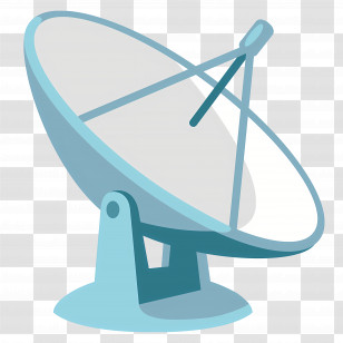
Aerials Remote Radio Head Block Diagram LTE Antenna Interface Standards Group - Text - Microwave Amplifier PNG
. The resolution of this PNG file is 745 x 835 pixels and it has a file size of 35.00 KB.Aerials Remote Radio Head Block Diagram LTE Antenna Interface Standards Group - Text - Microwave Amplifier PNG
You might also like these images below...