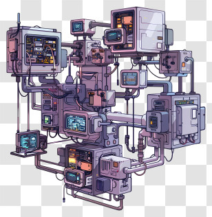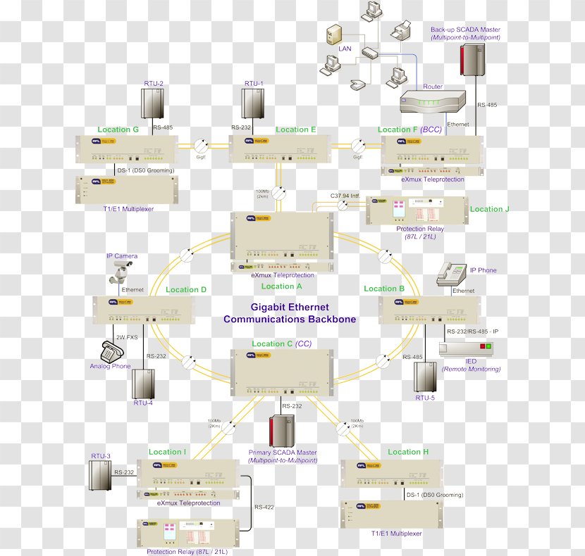
A diagram of a Gigabit Ethernet Communications Backbone. It shows the layout of the backbone, which is a device used to connect multiple devices to a network. The diagram is divided into two sections, with the top section showing the location of the device and the bottom section showing its connections. The device is located on the left side of the diagram, and the connections are connected to it on the right side. There are several other devices connected to the device, such as a router, a modem, and a modem. These devices are likely used to communicate with each other through the backbones. The connections are represented by yellow lines, which represent the connections between the devices. The diagram also includes labels for each device, indicating their purpose and how they are connected.
User lexusger uploaded the image
User lexusger uploaded the image
Multiplexer Diagram Relay Computer Network Ethernet - Internet Protocol - Power Substation Schematics PNG
. The resolution of this PNG file is 616 x 790 pixels and it has a file size of 331.17 KB.Multiplexer Diagram Relay Computer Network Ethernet - Internet Protocol - Power Substation Schematics PNG
You might also like these images below...